


Mô tả sản phẩm: Node quang EX-8604HB
1. Summary
1. EX8604G and EX7504G series of 1310nm optical relay station is a two-way optical connector with HFC network engineering experience and equipment development experience accumulate for many years by ourselves only for HFC two-way Broadband Network. This product is designed with full consideration of network topological structure.
2. The building block system modularized structure is adopted in EX8604H Series Field Optical Work station. It has flexible configuration and convenient debugging, and solves engineering and technical problems of collecting noise with two-way return path network. And it meets the requirements of modern CATV business network security transmission with high reliability of FTTB (Fiber to the Building).
3. EX8604HA and EX7504HA Optical Workstation are four way independent output models; EX-8604HB and EX-7504HB Optical Workstation are two way independent output models.
4. EX8604HJ Optical Workstation is our latest flagship product. Advanced optical AGC control circuit adds to the part of optical receiving to ensure the input optical power as low as -9dBm.
2. Performance Characteristic
n
Optical detector with low noise and high sensitivity is used in the part of downlink optical receiving, FP laser with high performance s used in the part of uplink transmitting, GaAs power double module with excellent nonlinear index in the output stage. Two optical receiver modules, one return optical transmitter modules , one network management transponder and one power supply modules can be configured in the internal structure at the most to improve the reliability and security effectively.
n
Two Way Optical Receiver Module is set to automatic switching or manual switching according to the requirement. Switching power supply hot backup module can de switched on line automatically.
n
Each down RF channel amplified independently by power double module can output 104 dBμV high lever signal, each road can be enlarged by a new GaAs power double module independently. The output lever and diagonal of each road are adjustable independently. About 100 end user are drove directly when there are no delayed amplification of preamplifier and user amplification.
n
Lug-in duplex filters, plug-in fixed equalizer, plug-in fixed attenuator scientific and reasonable test port adopted in EX8604HA (B) and EX7504HA (B) products make it easer to debug engineering.
n
The advanced optical AGC control circuit is used in the part of optical receiving of WR8604HJ product to reduce the optical power to -8dBm; The circuit for RF is improved, so the inserts of attenuators and equalizers are in common use. It makes it is more easy to debug projects and maintain lines.
n
Effective status monitoring circuit in which transponder meeting network management standards called (GB / T 20030-2005 HFC Network Equipment Management System) Standard can de disposed is built in it. So remote network management monitoring for equipment is easily implemented. So it can be suitable for front-end management software of other manufacturers.
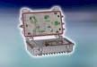
3. Block Diagram


4. Technical Parameters
|
Items |
Unit |
Technical Parameters |
|||
|
EX7504HA EX8604HA |
EX7504HB EX8604HB |
EX8604HC |
|||
|
Forward Path |
|||||
|
Optical Parameters |
|||||
|
Received Optical Wavelength |
nm |
1100 ~ 1600 |
|||
|
Received OpticalPowerRange |
dBm |
-5 ~ +2 |
-9 ~ +2 |
||
|
Recommended Range |
dBm |
-3 ~ +1 |
|||
|
Optical Fiber Type |
|
Single-mode |
|||
|
Optical Fiber Connector Type |
|
FC/APC或SC/APC |
|||
|
Optical Return Loss |
dB |
> 45 |
|||
|
Link Parameters |
|||||
|
C/N |
dB |
≥ 51 |
|||
|
C/CTB |
dB |
≥ 65 |
|||
|
C/CSO |
dB |
≥ 60 |
|||
|
RF Parameters |
|||||
|
FrequencyRange |
MHz |
45/87 ~750/862 |
|||
|
Flatness in Band |
dB |
±0.75 |
|||
|
Nominal Output Level |
dBμV |
≥104 |
≥102 |
≥108 |
|
|
Max Output Lever |
dBμV |
≥ 108 |
≥ 108 |
≥ 112 |
|
|
Output Return Loss |
dB |
≥16(45~550 MHz);≥14(550~862 MHz) |
|||
|
Output Impedance |
Ω |
75 |
|||
|
Return Path |
|||||
|
Optical Parameters |
|||||
|
Optical Emission Wavelength |
nm |
1310±10 |
|||
|
Laser Type |
|
FP or DFB |
|||
|
Output Optical Power |
mW |
1 ~3 |
|||
|
Optical Connector Type |
|
FC/APC、SC/APC (It is up to users) |
|||
|
RF Parameters |
|||||
|
FrequencyRange |
MHz |
5 ~ 30/65 (It is up to users) |
|||
|
Link Flatness |
dB |
±1.5 |
|||
|
Input Level |
dBμV |
75 ~ 85 |
|||
|
Input Return Loss |
dB |
≥16 |
|||
|
Output Impedance |
Ω |
75 |
|||
|
NPRDynamicRange |
dB |
≥10(NPR≥30 dB) |
|||
|
General Characteristics |
|||||
|
Supply Voltage |
V |
AC 135~250(50 Hz)或AC 35 ~ 90 (50 Hz) |
|||
|
Power Consumption |
W |
≤70 |
|||
|
Operating Temperature |
℃ |
-30 ~ +70 |
|||
|
Storage Temperature |
℃ |
-30 ~ +70 |
|||
|
Relative Humidity |
% |
Maximum 95% non-condensing |
|||
|
Dimension |
mm |
430(L)* 250(W)* 160(H) |
|||
★Special Notice:
The performance parameters of this manual according to GY/T 194-2003 <CATV system optical workstation technical requirements and methods of measurement> .We get it under the following testing environment.
★Testing Environment:
1.Down optical receiver part :Together with Standard 1550nm External Modulation Optical Transmitter,10km standard optical fiber and optical passive attenuator make the testing circuit .Set with 59 PAL-D analog TV channel signal at range of 47 MHZ ~550MHZ in the fix index loss of circuit, transmit digital TV signal at rang of 550MHZ~862MHZ ,the electricity(8 MHZ bandwidth) digital signal is 10dB lower than analog signal of carrier electricity level. When the input of optical receiver is -1dBm, RF output lever is 104 dBμV , measure C/CTB,C/CSO,C/N.
2. Uplink optical transmitter part: Link Flatness and noise Power Ratio (NPR) dynamic range are circuit index made up by uplink optical transmitter and uplink optical receiver.
★Tips:
The RF signal should be set to be 9~12dB incline output in practical engineering applications for suggestion in order to improve nonlinear index of cable transmission system under optical contactor.
5. Optional Options
Option1: Network Management Module
Option2: Network Management Transponder
Option3: Optical receiver backup module
Option4: Return optical transmitter module (FP laser with isolator are recommended)
Option5: Switching power supply hot backup module
6. Ordering Guide
The defaulted configuration is two-way provided configuration (One optical receiver module and one switching power supply module);If you need others, please tell us with the downlink, uplink division frequency of two-way channel when ordering.
